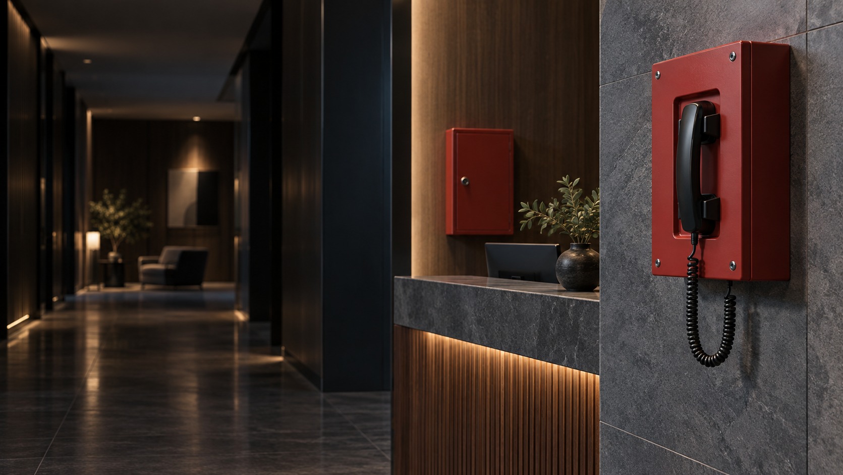
Wall-mounted emergency-communication handset station – Emergency Communication in Kuching & Sarawak (illustration)

Emergency Communication in Kuching & Sarawak

Plan a building emergency-communication path from the call point to its responsible operator. HJ coordinates supported stations, central equipment, power and interfaces under the approved scope. Ordinary intercom, mobile messaging and general networking are not substitutes for the building emergency system or its formal acceptance.

System selection and integration guideEmergency / Life Safety
Life SafetyEmergency Communication
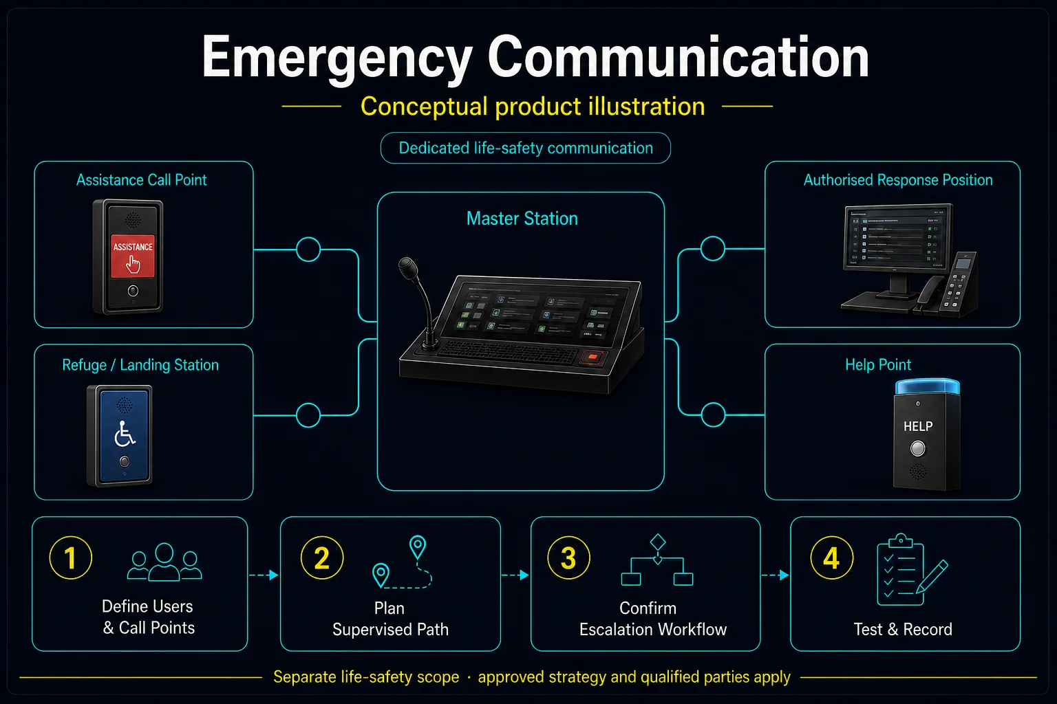
Emergency Communication system diagram
  1. 01Emergency Communication
  2. 02Site fit, interfaces and verification
  3. 03Warning interface
  4. 04mains-fail and duration test
Conceptual Emergency Communication product and system illustration.
Illustration & scope boundary

Conceptual Emergency Communication product and system illustration for Life Safety. Final device form, model, interfaces and quantities are confirmed from the assessed scope and approved product data. Conceptual monitored life-safety path for Emergency Communication, derived from this page's scope, interfaces and acceptance record.

Conceptual planning path — not an as-built drawing or project photograph.

What Emergency Communication covers

Plan a building emergency-communication path from the call point to its responsible operator. HJ coordinates supported stations, central equipment, power and interfaces under the approved scope. Ordinary intercom, mobile messaging and general networking are not substitutes for the building emergency system or its formal acceptance.

It sits in Emergency / Life Safety under Life Safety. The final deliverable is shaped by the intended outcome, the installed or proposed environment and the interfaces that must be owned, supplied, integrated and tested.

When to use this page

Approved emergency strategy, station locations, central operator, equipment platform, power needs, specialist drawings and the required acceptance route.
Typical environments to assess

  • Buildings with an approved emergency-communication requirement.
  • Defined station-to-control-room communication paths.
  • Specialist-coordinated life-safety works.

Engineering SOP & Handover Checklist

From the initial brief to the handover record: what to prepare, check and confirm with HJ.

01

Operational Purpose & Workflow

Plan a building emergency-communication path from the call point to its responsible operator. HJ coordinates supported stations, central equipment, power and interfaces under the approved scope. Ordinary intercom, mobile messaging and general networking are not substitutes for the building emergency system or its formal acceptance.

02

Pre-Attendance Evidence

Approved emergency strategy, station locations, central operator, equipment platform, power needs, specialist drawings and the required acceptance route.

03

Diagnostic & Testing Path

Identify station, central equipment, power, network and fire/safety interfaces with the appointed designers and specialists. State who answers, escalates, restores and maintains the system.

04

System & Responsibility Boundary

Conduct authorised call, location identification and agreed fault/power-path checks under the specialist test plan. Do not trigger live emergency operations without an approved procedure.

05

Acceptance & Handover Record

Retain station schedules, approved interface drawings, witnessed test records, operator training and outstanding actions.

Engineering Scope, Regulatory & Service Boundaries

Responsibility and evidence boundary

HJ coordinates assessment, engineering, installation, integration, testing and lifecycle support only for the scope recorded in the quotation. ISD handles catalogue, model, datasheet, supply and availability enquiries. Customer, consultant, builder and appointed-specialist responsibilities remain explicit.

Regulated or multi-discipline work proceeds only after site assessment and confirmation of the competent, qualified or appointed persons, approvals, safe isolation and responsibility required for that scope.

This focused topic remains connected to its complete system owner. Final models, quantities, interfaces and included work are confirmed in the assessed quotation.

Questions before proceeding

Use the answers as a planning boundary; site conditions and written scope remain decisive.

Can a normal intercom replace emergency communication?

Not by default. The approved building strategy, supported system and relevant specialist/authority acceptance determine the required communication path.

Which interfaces and responsibilities need confirmation?

Identify station, central equipment, power, network and fire/safety interfaces with the appointed designers and specialists. State who answers, escalates, restores and maintains the system.

What is checked and retained at handover?

Conduct authorised call, location identification and agreed fault/power-path checks under the specialist test plan. Do not trigger live emergency operations without an approved procedure. Retain station schedules, approved interface drawings, witnessed test records, operator training and outstanding actions.

Planning Emergency Communication? Tell HJ about your site

Tell us where it will be used, what it needs to do and what equipment you already have. HJ will recommend the right system, explain who is responsible for what, and agree the next step with you.