Operational purpose
Fiber Backbone & Building Fiber focuses on Fiber Infrastructure. Creates measured optical paths between endpoints through a controlled route, splice, termination and optic plan.
Building-to-building, campus and backbone optical-fiber infrastructure. This page focuses on Fiber Infrastructure within Fiber Optic, with site inputs, interfaces, verification and responsibility kept visible.
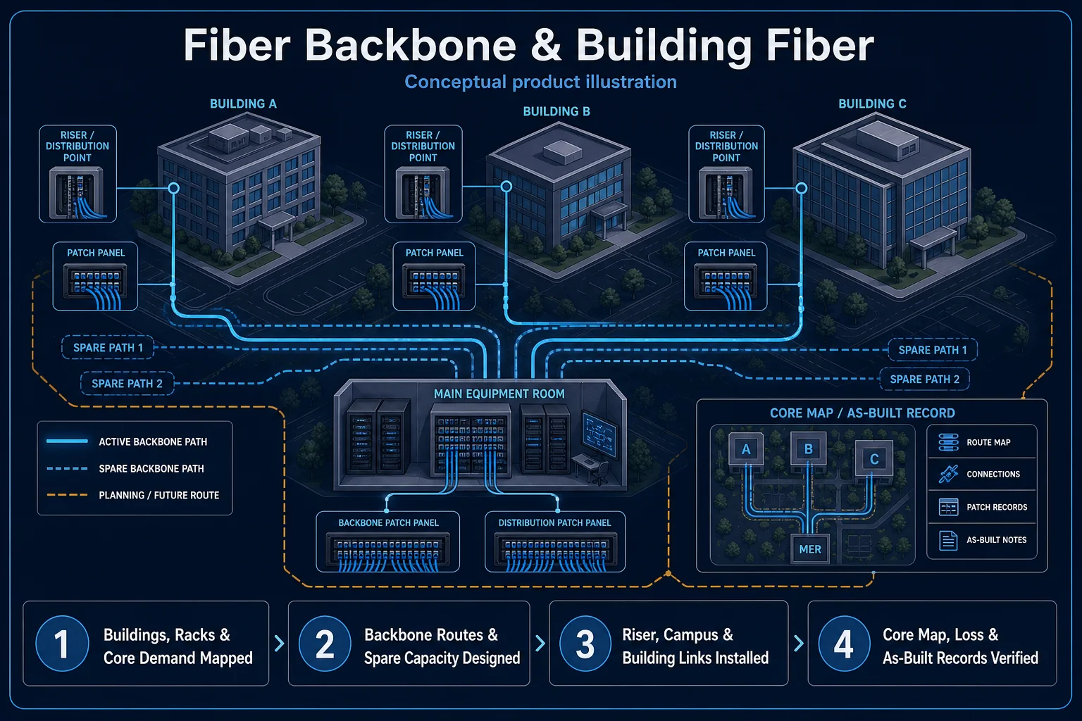
Conceptual Fiber Backbone & Building Fiber product and system illustration for Fiber Infrastructure. Final device form, model, interfaces and quantities are confirmed from the assessed scope and approved product data. Conceptual transport and endpoint path for Fiber Backbone & Building Fiber, derived from this page's scope, interfaces and acceptance record.
Conceptual planning path — not an as-built drawing or project photograph.
Building-to-building, campus and backbone optical-fiber infrastructure.
It sits in Fiber Optic under Fiber Infrastructure. The final deliverable is shaped by the intended outcome, the installed or proposed environment and the interfaces that must be owned, supplied, integrated and tested.
Use this page when Fiber Backbone & Building Fiber is the specific system decision, not merely one line inside a wider Fiber Optic quotation. Its exact focus is Fiber Infrastructure. Assessment records route, distance and endpoints, fiber type, core count and loss budget, splices, connectors, optics, containment and restoration margin and closes with core continuity and polarity, power level or loss result, OTDR, active-link, route and port records. Adjacent Fiber Optic options may share infrastructure while requiring different capacity, interfaces, operating rules or evidence, so the selection and handover result remain independently reviewable.
Use these four records to keep Fiber Backbone & Building Fiber distinct from adjacent systems or service tasks.
Fiber Backbone & Building Fiber focuses on Fiber Infrastructure. Creates measured optical paths between endpoints through a controlled route, splice, termination and optic plan.
For Fiber Backbone & Building Fiber, record route, distance and endpoints, fiber type, core count and loss budget, splices, connectors, optics, containment and restoration margin; add topology, capacity, routes, optical or copper budget, PoE, addressing, segmentation, credentials and outage ownership.
Optical performance depends on bend control, cleanliness, splice quality and compatible optics; core continuity alone is insufficient acceptance. Carrier, RF, cabling, switching, routing and application performance are different domains and cannot be accepted from a single online indicator.
Accept Fiber Backbone & Building Fiber with core continuity and polarity, power level or loss result, OTDR, active-link, route and port records; retain link or optical results, coverage or throughput samples, configuration backup, labels, port or core schedules and demarcation records.
These checkpoints make this page specific to Fiber Backbone & Building Fiber rather than a generic keyword page.
Define Fiber Infrastructure as the operating result for Fiber Backbone & Building Fiber, including the users, process and exceptions it must serve.
For Fiber Backbone & Building Fiber, confirm route, distance and endpoints, fiber type, core count and loss budget, splices, connectors, optics, containment and restoration margin.
Map Source & uplink → Core transport → Distribution edge → Managed endpoint for Fiber Backbone & Building Fiber and identify every interface owned by HJ, the customer, ISD supply or an appointed specialist.
Optical performance depends on bend control, cleanliness, splice quality and compatible optics; core continuity alone is insufficient acceptance. Final models, capacities and quantities still follow survey, compatibility and availability.
For Fiber Backbone & Building Fiber, record core continuity and polarity, power level or loss result, OTDR, active-link, route and port records; also agree link, throughput or power test, addressing and segmentation record, label, route and handover schedule before handover.
HJ coordinates assessment, engineering, installation, integration, testing and lifecycle support only for the scope recorded in the quotation. ISD handles catalogue, model, datasheet, supply and availability enquiries. Customer, consultant, builder and appointed-specialist responsibilities remain explicit.
Final scope, quantities, compatibility, access, programme, availability and responsibility are confirmed during assessment and quotation.
This focused topic remains connected to its complete system owner. Final models, quantities, interfaces and included work are confirmed in the assessed quotation.
Use these routes to move from this focused record into the complete system, site, capability and aftercare journey.
Use the answers as a planning boundary; site conditions and written scope remain decisive.
Fiber Backbone & Building Fiber focuses on Fiber Infrastructure within Fiber Infrastructure. Creates measured optical paths between endpoints through a controlled route, splice, termination and optic plan. The approved selection must respect this boundary: Optical performance depends on bend control, cleanliness, splice quality and compatible optics; core continuity alone is insufficient acceptance.
Confirm route, distance and endpoints, fiber type, core count and loss budget, splices, connectors, optics, containment and restoration margin. Record core continuity and polarity, power level or loss result, OTDR, active-link, route and port records, then complete link, throughput or power test, addressing and segmentation record, label, route and handover schedule against the approved scope.
No. HJ handles engineering, installation and integration. ISD handles product-family, model, datasheet, supply and availability enquiries separately.
Share the site, intended outcome, existing equipment and timing. HJ will confirm the correct system route, responsibility boundary and next step.