Installation package
Proactive Defence Plus and Electric Fence Planning in Sarawak
This combined direction considers video, independent alarm control and a separate electric-fence system around the same property. The layers address different needs and retain distinct equipment and installation responsibilities. A joined-up operating plan can be assessed without pretending the fence is a camera feature or that all interfaces already work together.
How this package fits together
Proactive Defence Plus with Electric Fence Canvas
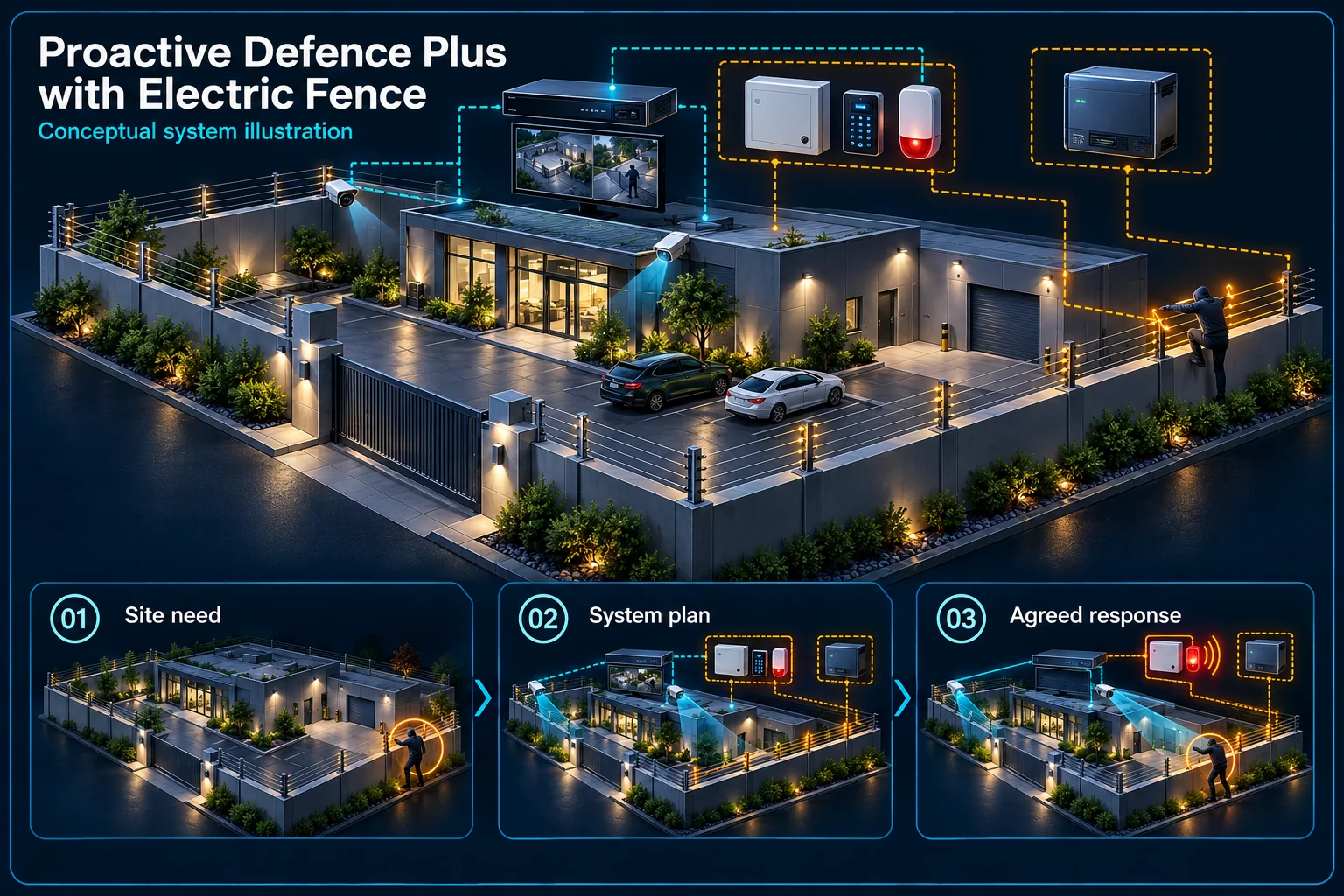
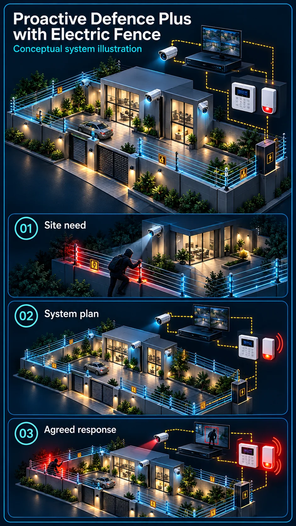
System planning notes
Three protection layers with separate responsibilities
Video, alarm control and the fence remain distinct systems; any bridge is shown as conditional.
- Solid line: illustrated functional path or agreed test route.
- Dashed line: optional device or compatibility to confirm.
- The fence layer is not a CCTV feature or a shared high-voltage wiring instruction.
- Dashed links require separately approved compatible interfaces and site commissioning.
Views, selected events and recording
Panel, keypad and independent siren
Own energiser and approved perimeter
Understands modes, evidence and response
Boundary, access and safety review
- E1: Approved site scope → Video layerObservation requirement
- E2: Approved site scope → Electric-fence layerIndependent fence design
- E3: Video layer → Alarm-control layerCamera-event interface if approved — optional / compatibility to confirm
- E4: Electric-fence layer → Alarm-control layerFence signal interface if approved — optional / compatibility to confirm
- E5: Alarm-control layer → Responsible operatorAgreed response procedure
Give each protection layer its own purpose
Video observes and supports review
Camera views should help an authorised person understand activity at entrances and agreed perimeter areas. Supported video events and local camera responses are configured for those views; a camera picture does not establish the electrical condition of the fence.
Fence and alarm have distinct controllers
The fence needs its own appropriate energiser, monitoring arrangement and approved perimeter design. The alarm panel provides independent arming and response logic. Neither controller should be treated as an interchangeable power source or a decorative extension of the CCTV diagram.
Review the actual property boundary
Survey physical access and surroundings
Identify ownership boundaries, gates, walls, vegetation, public access and maintenance needs. The site review must consider suitable placement and safety requirements before equipment is selected. Do not copy a neighbouring property's layout as a ready installation design.
Plan gates and ordinary authorised movement
Agree how users enter, how permitted work is handled and who restores each protection mode. Camera warning, alarm arming and fence operation may have different controls. The everyday sequence should be understandable to the people actually using the property.
Coordinate events only through approved interfaces
Distinguish parallel systems from linkage
Video, alarm and fencing can be installed as separate systems. Automatic transfer of a fence or camera event to another controller needs a specifically compatible interface and configuration. Co-location or matching brand names do not prove this path.
Keep optional warning equipment separate
An Air Horn or additional strobe is another output request, not automatically part of the combined plan. Confirm its purpose, trigger, power arrangement and impact on neighbours. This page does not provide a high-voltage or site wiring instruction.
Accept each layer and the agreed coordination
Test the systems individually
Commission the fence under its approved procedure and verify CCTV views, recording and the independent alarm's controls separately. Document the actual equipment and the responsible maintenance roles instead of treating one successful demonstration as acceptance of every layer.
Demonstrate confirmed event transfer
Where integration is included, verify the selected event, receipt at the intended controller, arming condition, output and reset. Explain network and backup-power dependencies. The result is an accepted site workflow, not a universal claim about all Plus and fence combinations.
Questions about Proactive Defence Plus with Electric Fence
Is the electric fence powered by the CCTV system?
No such arrangement is assumed. The fence is an independent system with its own approved energiser, safety and installation requirements. Any signal interface must be specifically designed.
Will a fence event automatically display the right camera?
Only if the selected equipment and platform support that configured workflow. Event-to-video association is a distinct integration item that needs demonstration.
Can I request video and fencing without automatic linkage?
Yes. A parallel-system design can be assessed. The scope should explicitly distinguish independently operating equipment from any approved and tested coordination.