System feature
External Air Horn & Strobe: Optional Response-Device Planning
An external air horn or additional strobe is a separate response-device option, not a universal camera accessory. HJ reviews the required warning purpose, compatible control path, suitable power arrangement and installation conditions before including either item in an approved system scope.
How this feature fits together
External Air Horn & Strobe Canvas
System planning notes
One trigger path, a separate power path, optional devices
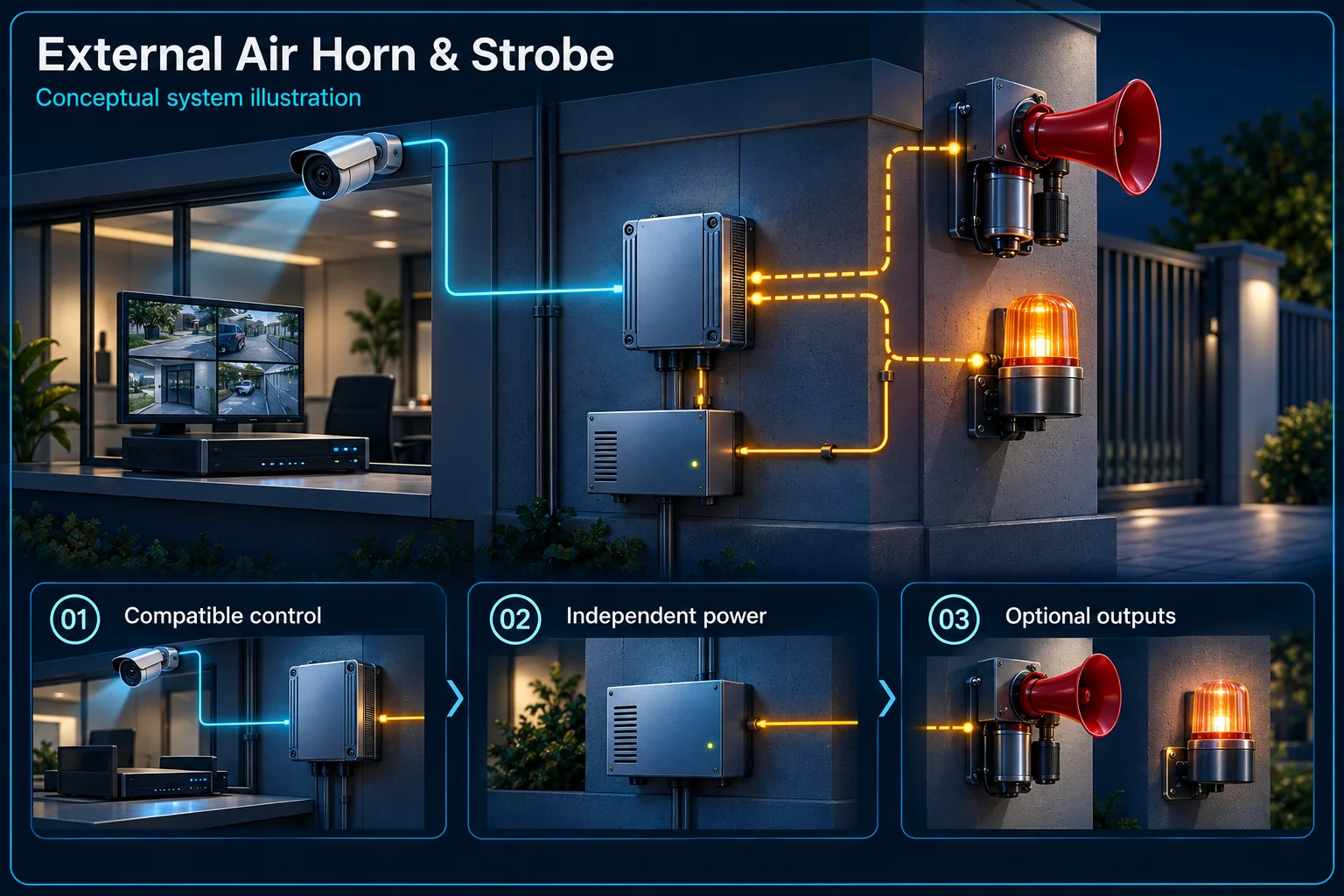
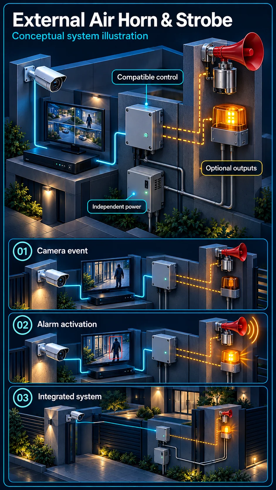
The horn and strobe remain optional. The control interface and supply are selected for the actual equipment.
- Solid line: illustrated functional path or agreed test route.
- Dashed line: optional device or compatibility to confirm.
- Dashed control links are optional and require compatibility confirmation.
- Power and trigger paths are distinct; this is not a construction wiring diagram.
Supported target, rule and schedule
Approved interface and protection
Load and installation to assess
Own activation and stopping test
Own visibility and schedule review
- E1: Qualifying event → Compatible controlSupported trigger — optional / compatibility to confirm
- E2: Compatible control → Optional air hornOptional control path — optional / compatibility to confirm
- E3: Compatible control → Additional strobeOptional control path — optional / compatibility to confirm
- E4: Selected supply → Optional air hornSeparate designed power
- E5: Selected supply → Additional strobeSeparate designed power
Define why an additional device is needed
Supplementing a camera is a separate requirement
A customer may want a warning at a different position from the camera's own output. Identify the area, intended audience and operating period first. An external device must not be assumed to be included simply because the reference plan contains Proactive, Defence or Plus in its name.
Sound and visual warning serve different users
Consider what the sound or light should communicate to an authorised operator or person nearby. Review normal working activity, neighbours and conditions at the mounting position. More conspicuous output is not automatically a more suitable response for every premises.
Confirm the control and power design
The trigger needs a compatible interface
A camera event, relay or controller output must be assessed against the external device and approved interface. The exact arrangement needs appropriate protection and installation review. This concept diagram does not authorise direct connection of an arbitrary horn or lamp to a camera terminal.
Power is a different path from the event signal
The device's supply, load and any supporting control equipment require separate selection. Review the proposed cable route, environment, mounting and maintenance access. Where backup operation is requested, identify its actual loads rather than treating the event link as a power source.
Manage activation and restoration
Use an agreed schedule and output rule
Choose which supported event is permitted to activate the device and under which armed conditions. Normal visitors, cleaners or vehicle movement should be considered in that rule. A target classification by itself is not enough to decide that a warning is appropriate.
Provide an authorised stopping procedure
The operator needs a defined way to silence, suspend or reset the chosen output and return to the agreed mode. Review how faults and maintenance are handled. Do not create an unmanaged warning that staff cannot safely interpret or control.
Commission it as an individual output
Demonstrate the full trigger-to-output chain
Test the qualifying event, receiving controller, physical output and reset behaviour under controlled conditions. Check the relevant non-trigger or disarmed case as well. Demonstrating only the camera speaker does not verify an external horn, strobe or its independent power arrangement.
Document what is included and who maintains it
Record the selected device, control path, installation boundary and accepted behaviour in the scope and handover. Optional equipment remains a request until approved. A completed installation record, not this planning page, establishes what was actually supplied and tested.
Questions about External Air Horn & Strobe Integration
Are Air Horn and Additional Strobe included in every Plus plan?
No. They are optional response-device requests. Their compatibility, equipment, power and installation scope must be assessed and approved separately.
Can the horn use the camera's power terminals?
Do not assume that. The electrical and control requirements of both devices must be checked through an appropriate design. This page is a functional illustration, not a direct wiring guide.
Can an external strobe flash for every motion event?
A suitable rule needs to account for the supported event, authorised activity and operating time. Review an appropriate schedule and demonstrate the intended behaviour at handover.